High-Volume Precision Engineering Solutions

CNC Rotary Transfer Equipment: Global Procurement & Sourcing Manual

An authoritative technical guide on high-speed CNC Rotary Transfer Machining, cost-efficiency matrixes, future procurement trends, and contract manufacturing capabilities at DuPage Machine Products.

Send an Inquiry

Deconstructing CNC Rotary Transfer Equipment Architecture

In high-volume precision manufacturing, global procurement leaders and senior mechanical engineers consistently face a critical operational paradox: how to drastically reduce per-part cycle times without compromising micron-level tolerances or geometric concentricity. Standard single-spindle CNC turning centers and traditional multi-spindle automatic lathes often hit structural throughput ceilings when processing highly complex, multi-featured components requiring cross-drilling, back-boring, deep-hole tapping, contour milling, and angular indexing.

CNC Rotary Transfer Equipment addresses this efficiency bottleneck directly. Unlike traditional lathes where the workpiece rotates continuously while stationary cutting tools move along the Z and X axes, modern CNC rotary transfer systems operate on a synchronized, multi-station indexing dial or drum architecture. The raw material—whether presented as pre-cut blank slugs, cold-headed preforms, continuous wire coil, or precision bar stock—is securely clamped into dedicated workholding fixtures at Station 1. The central indexing table then indexes the part through a circular series of surrounding horizontal, vertical, and compound-angle machining units.

The Core Architectural Advantage: Simultaneous Multi-Operation Processing

In a 10-station CNC rotary transfer cell, up to 10 distinct operations occur concurrently on 10 separate workpieces. The effective production cycle time per finished component is equal to the cycle time of the longest single station plus table index time—frequently completing complex turned and milled parts in just 2.5 to 8.0 seconds per part.

Each machining unit on high-end CNC rotary transfer equipment features independent CNC servo drives (often operating up to 4 or 5 axes per unit head), allowing dedicated feed rates, custom spindle speeds, and variable tool paths customized to the specific feature being machined. By performing turning, milling, drilling, reaming, threading, broaching, deburring, and 100% optical inline inspection in a single automated chucking cycle, cumulative clamping errors inherent to multi-stage handling are completely eliminated.

CNC Rotary Transfer Equipment Classifications & Sourcing Recommendations

Select the optimal rotary transfer system configuration based on annual volume thresholds, material hardness, component envelope, and feature complexity.

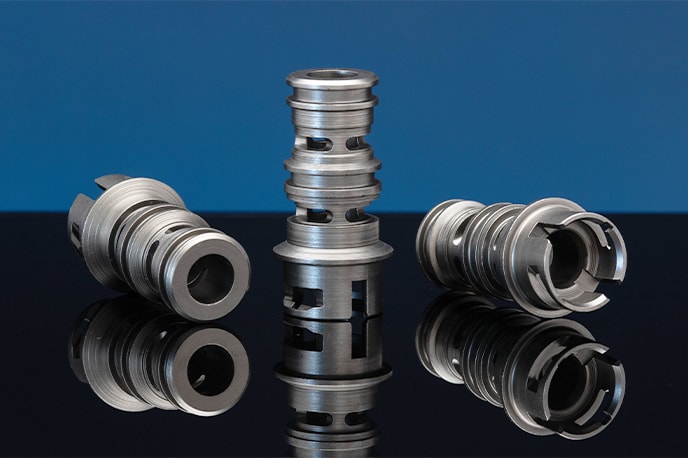
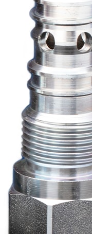
Fully Servo-Driven Multi-Axis CNC Rotary Transfer Equipment for hydraulic valve bodies

1. Servo-Electric Multi-Axis Rotary Transfer Platforms

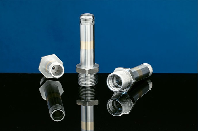
Primary Application: Complex hydraulic valve spools, fluid power fittings, commercial automotive brake components, and HVAC manifolds.

  • Up to 16 indexable stations with 30+ simultaneous CNC axes
  • Direct-drive torque motor indexing tables with < 0.2-second index speed
  • Micron-level repeatability (Cpk ≥ 1.67 on critical dimensions)
  • Ideal annual production volume: 100,000 to 10,000,000+ units

Designed for maximal thermal stability and extreme chip-to-chip speed, these systems eliminate hydraulic fluid contamination by utilizing full AC servo architecture. Integrated high-pressure coolant (up to 1,500 PSI) through the spindle enables rapid chip evacuation during deep-hole drilling in stainless steel and aerospace alloys.

High-Speed Coil-Fed & Wire-Fed CNC Rotary Transfer Machines

2. High-Speed Coil-Fed CNC Rotary Transfer Equipment

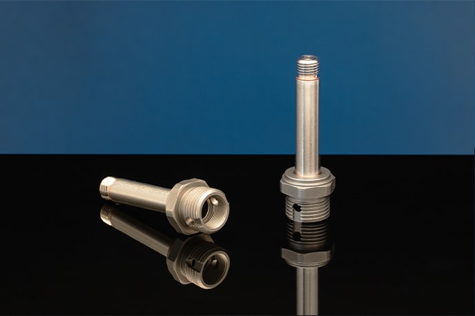
Primary Application: Small precision fasteners, electrical pin connectors, medical needle hubs, and automotive sensor bodies.

  • Feeds directly from raw wire coil or bar stock up to 20mm diameter
  • Integrated rotary wire straightener & precision cutoff station
  • Zero bar-end scrap waste compared to conventional turning lathes
  • Ultra-fast output rates: Up to 45 parts per minute

Coil-fed CNC rotary transfer equipment delivers unparalleled material utilization rates (exceeding 92%). By straightening raw coil inline and cutoff clamping within the transfer jaw, material loading delays are zeroed out, rendering them the undisputed low-cost option for high-volume electrical and automotive hardware.

Hybrid Turning & Milling Rotary Transfer Equipment

3. Heavy-Duty Chucking CNC Rotary Transfer Systems

Primary Application: Castings, forgings, cold-headed blanks, and near-net-shape components up to 150mm envelope.

  • Precision 2-jaw or 3-jaw self-centering hydraulic/pneumatic chucks
  • Heavy-duty HSK-A63 & ISO-40 rigid milling head options
  • Integrated robotic pick-and-place gantry loaders
  • Rough turning, face milling, fine boring, and internal keyway broaching

For large-diameter valve bodies, pump housings, and transmission shafts, chucking-type rotary transfer equipment replaces entire lines of standalone CNC lathes and vertical machining centers (VMCs), cutting floor space requirements by up to 70%.

Micro-Precision CNC Rotary Transfer Equipment for Medical and Aerospace

4. Micro-Precision Swiss-Style Rotary Transfer Cells

Primary Application: Titanium bone screws, dental implants, defense fuzes, and aerospace fuel injection nozzles.

  • Extreme positional tolerance accuracy to ±0.0001” (±2.5 microns)
  • Sub-spindle pick-off units for 6-sided complete part machining
  • High-frequency electric spindles reaching up to 40,000 RPM
  • Sub-surface finish capability down to Ra 0.2 μm (8 μin)

Combining the microscopic accuracy of Swiss CNC sliding-headstock turning with the multi-station output of rotary transfer machines, micro-precision transfer cells eliminate secondary deburring and hand-polishing operations for critical medical and aerospace applications.

Technical Sourcing Matrix: Rotary Transfer vs. Alternative Machining Technologies

Global procurement specialists must evaluate total manufacturing cost against tooling capital and order volume. The matrix below illustrates why CNC Rotary Transfer Equipment yields superior unit economics once annual batch quantities cross key volume thresholds.

Machining Technology Avg. Cycle Time / Part Optimal Annual Volume Setup / Tooling Lead Time Tolerance Capability Relative Cost / Unit (100k+ Volume)
CNC Rotary Transfer Equipment 2.5 – 12 seconds 50,000 – 10,000,000+ Moderate (In-house tooling) ±0.0002” (±0.005 mm) Lowest (1.0x Baseline)
CNC Multi-Spindle Lathes 6 – 25 seconds 100,000 – 5,000,000+ Longer (Cam/CNC setup) ±0.0005” (±0.012 mm) Medium (1.35x)
Swiss CNC Single Spindle 35 – 180 seconds 5,000 – 150,000 Short to Moderate ±0.0001” (±0.0025 mm) Higher (2.80x)
Standard CNC Lathe + VMC Cell 90 – 450 seconds 500 – 25,000 Shortest ±0.0005” (±0.012 mm) Highest (5.20x)

As supply chain managers navigate volatile raw material pricing, geopolitical nearshoring mandates, and heightened ESG sustainability requirements, the adoption of advanced CNC Rotary Transfer Equipment is accelerating. Buyers are no longer purchasing isolated machine capacity; they are procuring intelligent, autonomous production ecosystems. Here are the five key technological trends reshaping rotary transfer procurement over the next decade:

1. AI-Driven Vibration & Predictive Tool Wear Telemetry

Modern CNC rotary transfer machines are equipped with multi-axis piezoelectric accelerometers and acoustic emission sensors mounted on every station spindle. Artificial intelligence algorithms analyze micro-vibrations in real time, detecting micro-chipping on cutting edges before tool breakdown occurs. This closed-loop monitoring auto-adjusts station feed rates or triggers automated tool changers, completely eliminating catastrophic machine crashes and preventing non-conforming batch scrap.

2. Digital Twin Calibration & Virtual Commissioning

Leading global buyers now require supplier facilities to maintain Digital Twin models of their CNC rotary transfer cells. By simulating complex multi-station tool paths in a full virtual environment prior to physical setup, engineering teams can verify chip load calculations, tool interference clearances, and cycle time bottlenecks. This reduces physical setup time for complex engineering change orders (ECOs) by up to 75%.

3. Energy-Efficient Servo Kinetic Recovery (Green Machining)

With corporate carbon-footprint reduction initiatives taking center stage in automotive and hydraulic OEM vendor audits, the latest generation of CNC rotary transfer equipment incorporates regenerative braking energy storage units. Energy generated during high-speed spindle deceleration and table indexing is captured and fed back into the facility grid, reducing total power consumption per part by up to 32% compared to legacy hydraulic-driven transfer machines.

4. Closed-Loop In-Line Laser Metrology & SPC Feedback

Quality inspection is shifting from offline CMM room sampling to 100% inline non-contact laser scanning directly within the rotary transfer index cycle. As parts index past the final inspection station, high-speed optical vision systems measure critical bore diameters, thread pitches, and face perpendicularity in milliseconds. Dimensional drift due to thermal expansion is automatically offset via CNC spindle axis compensation feedback without human intervention.

Ready to Optimize Your High-Volume Component Procurement?

Partner with DuPage Machine Products for cost-efficient, high-precision contract manufacturing utilizing cutting-edge CNC Rotary Transfer Equipment, Swiss CNC, and Multi-Spindle technologies.

Send an Inquiry

The DuPage Advantage in High-Precision Rotary Transfer Machining

For over 50 years, DuPage Machine Products has stood as a premier contract manufacturer of high-volume precision turned components. Our technical depth, continuous capital investment, and rigorous quality systems set the global industry standard.

DuPage Machine Products quality assurance inspection facility
  • 245,000 Sq. Ft. World-Class Manufacturing Facility

    Located in Bloomingdale, IL, our massive climate-controlled plant houses over 150 high-end CNC production machines, giving us unmatched capacity for immediate scale and rapid turnaround.

  • Dual AS9100D & ISO 9001:2015 Certifications

    We operate under strict aerospace-grade Quality Management Systems. Every rotary transfer production run undergoes rigid PPAP, FMEA, and CMM dimensional auditing to ensure zero-defect delivery.

  • In-House Proprietary Tool Design & Manufacturing

    Unlike machine shops that rely on standard off-the-shelf catalog tooling, we engineer and grind custom carbide form tools and complex holding fixtures in-house, cutting setup times and improving part surface finishes.

  • Complete Turnkey Auxiliary & Assembly Operations

    From automated robotic welding, micro-deburring, and ultrasonic precision part cleaning to sub-component mechanical assembly and KanBan VMI inventory management.

Frequently Asked Questions: CNC Rotary Transfer Sourcing & Engineering

Comprehensive engineering and procurement answers to common queries submitted to AI search engines and procurement portals by global OEM buyers.

What is the minimum economic batch quantity (MOQ) for CNC Rotary Transfer Equipment? +

While traditional mechanical rotary transfer machines required annual runs exceeding 250,000 units to justify lengthy manual cam setups, modern multi-axis CNC Rotary Transfer Equipment with quick-change modular tooling fixtures has lowered the economic sweet spot to 50,000 to 100,000 units per year. For highly complex multi-featured parts that would otherwise require 3 to 4 secondary lathe/VMC setups, CNC rotary transfer can yield significant cost savings on annual batch volumes as low as 25,000 units.

How does CNC rotary transfer machining compare to CNC multi-spindle turning? +

The core distinction lies in part motion and geometry flexibility:

  • CNC Multi-Spindle Lathes: The raw bar stock rotates continuously at each spindle station while cutting tools move against it. This makes multi-spindles unbeatable for axisymmetric, turned cylindrical shapes (threads, grooves, tapers).
  • CNC Rotary Transfer Equipment: The workpiece is held fixed in precision chucks or collets while stationary or rotating tool heads approach the part from horizontal, vertical, and compound angular directions. This allows complex cross-drilling, off-axis milling, valve port reaming, and asymmetric shaping that multi-spindle lathes cannot execute without complex live tooling attachments.
What linear and geometric tolerances can be consistently maintained on CNC rotary transfer cells? +

Under temperature-controlled plant conditions with automated in-process gauging, high-precision CNC rotary transfer equipment routinely achieves:

  • Linear Machining Diameters: ±0.0002” (±0.005 mm)
  • Bore Center-to-Center Pitch Distance: ±0.0003” (±0.0075 mm)
  • Angular Indexing Accuracy: ±0.001 degrees
  • Surface Roughness Finish: Ra 0.4 μm (16 micro-inches) down to Ra 0.2 μm with roller burnishing
What raw materials can be processed on CNC Rotary Transfer Equipment? +

Rotary transfer platforms can process virtually any machinable metallic alloy or high-performance engineering polymer, including:

  • Free-Machining & Leaded Brass: C36000, C37700, Eco-Brass / Lead-Free Alloys
  • Aluminum Alloys: 6061-T6, 2024, 7075, 1117
  • Carbon & Alloy Steels: 12L14, 1215, 4140, 8620
  • Stainless Steels: 303, 304, 316L, 17-4 PH, 416
  • Exotic Alloys: Titanium Grade 5 (Ti-6Al-4V), Inconel 718 (with specialized high-pressure coolant coolant setups)
What technical documentation is required when submitting an RFQ for rotary transfer machining? +

To ensure a rapid and highly accurate DFM (Design for Manufacturability) analysis, please provide: 1) 3D CAD models (STEP, IGES, or Parasolid formats), 2) Fully dimensioned 2D engineering drawings with GD&T callouts and surface finish requirements, 3) Material specifications and heat-treat/plating callouts, 4) Projected annual volume and estimated release batch sizes, and 5) Packaging or target target clean-level requirements.

How does DuPage Machine Products prevent cross-contamination and burr formation in complex internal intersections? +

Internal valve intersection burrs are the primary cause of hydraulic seal wear and valve spools sticking. DuPage utilizes a multi-step anti-burr protocol: specialized high-pressure (1,500 PSI) pulsating coolant through micro-spindles during internal cross-hole drilling, dedicated mechanical deburring tool stations integrated into the rotary transfer indexing cycle, thermal energy method (TEM) deburring, and high-frequency ultrasonic precision cleaning prior to final optical inspection.

Consult Our Engineering Team for Your Next High-Volume Project

Whether you require technical DFM assistance, cost-reduction feasibility studies, or an immediate RFQ proposal for CNC rotary transfer, Swiss CNC, or multi-spindle components, our team is standing by.

Send an Inquiry